Still in development, so specs and features presented here are not final!
USB-C Amp-Meter V2
Bringing the (good old) amp meter to new levels:
- higher resolution: 20-bit analog-to-digital converter (versus 16 on the original) enables 20µA measurement resolution
- higher currents: that higher ADC resolution also raises current limit to 15A (peak), plenty
of headroom to power those PC gaming laptops.
As the PCB is still being designed, I have not finally decided on the maximum permanent current the meter can handle! - energy/charge: the new chip used also features energy and charge meters
- not limited to USB-C: the new PCB features additional power connectors with looped ID pin support, so you can finally connect like Dell power supplies and laptops
- new power design: the new power design enables standalone usage, while the first version was
solely powered through the USB data connection.
Additional circuitry prevents startup delays even in standalone mode (for instance when a PD charger is turned off when disconnected, like Apple's)
Other notable changes:
- improved form factor: V1 was more like an electronic design study, and featured an ESP8266
development board.
The new variant implements the microcontroller directly on the board, reducing the device's thickness - more accurate measurement due to improved noise-cancelling on the current shunt
This (of course) comes with a few drawbacks:
- I had to drop serial protocol compatibility with PLD's meter.
The enhanced resolution and additional measurements did not fit in either the data format (9 bytes) nor the baud rate (9600 previously).
This also means you have to use my OSD software (or roll your own). - higher price point: the new power measuring chip is twice as expensive as the old one, the
ESP8266's chip and supporting components are way more expensive than the old dev-board approach, and all the additional
power circuitry adds up. Plus I may need thicker copper on the PCB to account for the higher
current.
While the first version's components were less than 10 €, it seems version 2 is more like 25-30 € (only parts, no labour, no allocation of design costs).
I'm still undecided if I go for a larger display. Also I'm not proficient in 3d design, so there's still no decision on having a 3d printed case.
I'm looking for people interested in the new power meter, so I can order the second set of PCBs
and components accordingly.
Please drop me an
email if you are interested in acquiring the meter, and I'll keep you updated on the
progress.
Once version 2.0 is considered stable and good to go, there will be some shop link here and in your
inbox.
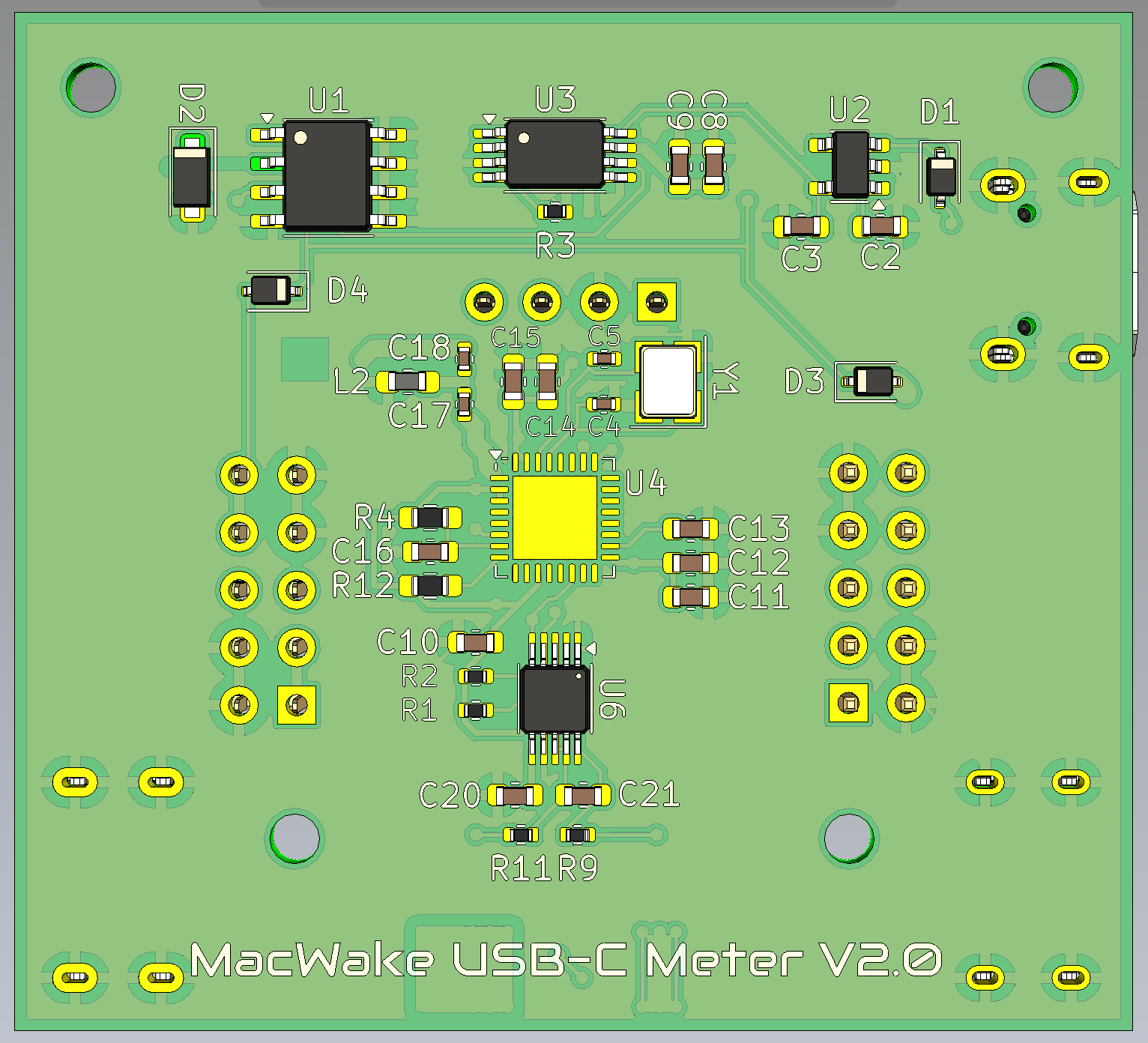 V2 PCB, back rendering
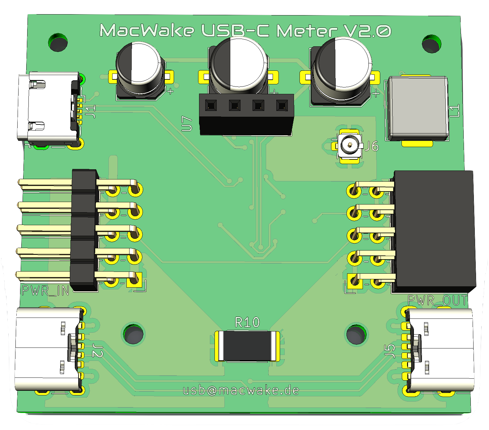 V2 PCB, front rendering
Update July 2025: I built a prototype of the new meter, and discovered I made some serious
engineering mistakes while moving the ESP8266 directly to the PCB.
I already corrected these by changing to an ESP32-C3 MCU. This move also reduced the bill of materials,
and enables the use of Bluetooth LE as an alternative to USB communication with the on-screen
display software. For that I also added an antenna connector to the PCB.
Because I needed new PCBs anyway, I modified the external power in/out connectors so that they work in
both directions and short circuits are less likely, and they can now safely run 6A steady (10A peak).
September 2025: I had to redo the software, this time using the Qt6 framework, because there were
all kinds of problems with using Bluetooth Low Energy (BLE) on Windows.
I'm still unsure if I keep the power supply from USB-C the way it is, or redo this part, this time with
an LDO. The parts are somewhat expensive, and the real current consumption is way less than the 200mA
the datasheets suggested - we're more in the 3–5 mA range, but without BLE. I'll revisit this once V1 is
complete and on sale.
March 2026: I tested version 3 of the PCB and software while repairing stuff, and it seems to work
fine.
Played around with Wi-Fi for over-the-air firmware updates, nearly bricked two boards 😒. Conclusion: you
just cannot do a good RF/antenna line with 50Ω on a two-layer PCB, at least not good enough for Wi-Fi.
Bluetooth on the other hand works like a charm; at least my MacBook didn't disconnect even 5m and two
doors away.
The OSD software is considered stable now, as is the GitHub-based build and release system. I even
managed to build a new feature for the OSD software: audible feedback on current consumption,
where the change in current defines the volume, and the absolute current defines the frequency. This way
you get a loud, high "blip" for high current spikes, while the volume is low (or even cut off) with
"normal" current draws. This is especially useful when you're hunting a short circuit: power management
shuts off immediately when it detects the short, but you only have two eyes and may have just pulled out
the thermal camera to find that nasty shorting cap.
I'm extremely happy that our friend JFIXX agreed to check the prototype out, looking forward to the first "external" critics and feedback.
April 2026: First testing by JFIXX revealed PD protocol problems with non-Apple devices 😔
I learned that Apple devices - contrary to my assessment - are much more tolerant when it comes to
interpreting the PD protocol than Android devices, for example. Once I get to the bottom of these
problems, I think there will have to be version 2.4 of the PCB. It remains exciting...
June 2026: Scrapped V2 🙁. While it works absolutely fine with MacBooks, JFIXX
tests didn't happen because of the problems with PD and/or fast-charging Android devices, and me
realizing I would need CE/RED approval for the whole product, including the radio/antenna design. This
is just ridiculous - even if I'd be able to sell 100 units, the certification would cost like 20.000 €,
which is 200€ per unit.
But there's also "good news": I shifted plans and am working on Version 3!