USB-C Amp Meter
This one is inspired by Paul Daniels's PLD USB-C meter, which he is no longer manufacturing.
Can now be purchased on eBay!!!I bought one myself, but found it to have a few little drawbacks: It sat flat on my bench, so I would always look at the display from a 50° angle. Also, because of how the lights are arranged here, it was not always easy to grasp when current spikes occured.
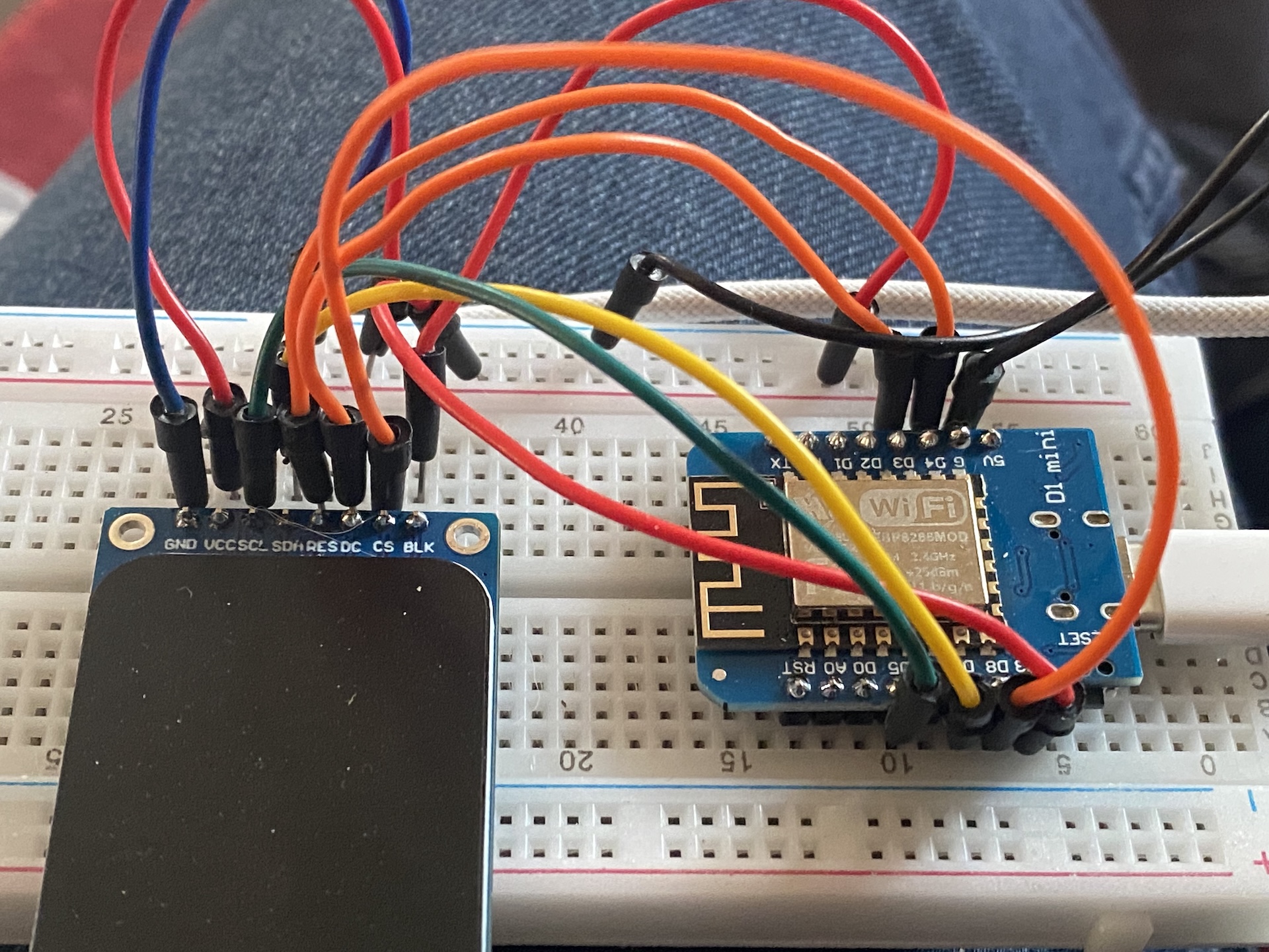 Experimenting with OLED display and ESP8266
I had some D1 Mini ESP8266 boards and a couple of different displays laying around for other projects or just to play with, so I tried to recreate PLD's invention, but with entirely different hardware.
At the heart of the amp meter is the INA226 (which could have also been an INA219 since I don't use the alert feature) by Texas Instruments. To make playing around with it easy, I used a WEMOS D1 Mini development board, and the first working firmware simply logged readings to it's serial port.
Speaking of the serial communication, I chose to be compatible with PLD's serial protocol, which I gathered from his usbc-meter project on Github. I first created an app using the Qt framework, that is able to communicate with PLD's meter (learning Qt while I was at it). I then created a firmware for the D1 Mini, that reads from the INA226, drives a 128x64 OLED display, and also writes to the serial port.
Still having issues with cross compiling the Qt app for Windows and Linux; also being forced to GPL my code when using Qt, I'm looking for a different framework to use. Currenty wxWidgets seems to be the most popular choice, but I'm struggling with getting it to work.
On the hardware side of things, I made the schematics with KiCad, designed version 1 of the PCB, and ordered a set of 5 at PCBWay. After a few tweaks I had a real working prototype to make further adjustments to the firmware:
- Display only voltage ratings instead of the raw measurements
While it is "nice" to see so much changing digits, I never had a use for this, as the power bricks I used always adhered to the Power Delivery standard voltages (+- a few %). Because of that, I decided to use and display only voltage "classes" (5V, 9V, 15V, 20V etc). On the OLED these are staggered across the top. -
Display peak current
Because I now had even more unused display areas, I decided to also display the peak current draw (of the last ~50 measurements) in that voltage class, as that was previously only available in the OSD. - Display current bars
As I sitll had some unused display area, I decided to display the current draw as a vertical bar. That was really easy to add, as I already had the max current reading to serve as the bar's maximum. I think this bar makes it easier to see current spikes.
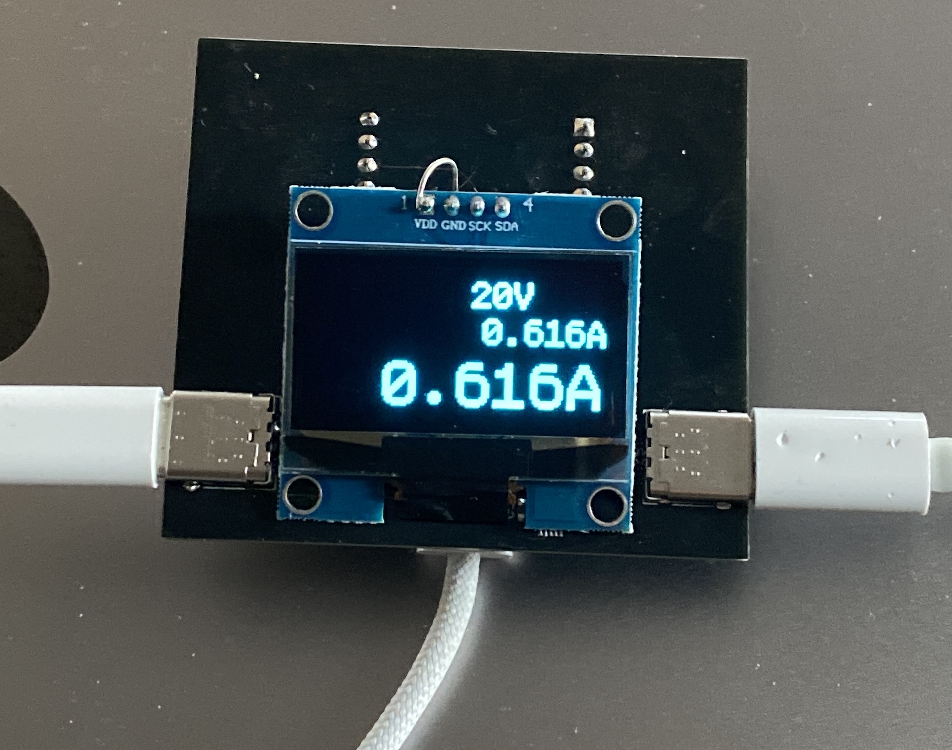
I found a coupple of mistakes in the design (like a too large shunt resistor value and mixed up Vcc/Gnd pins on the OLED), but I was able to fix them using donor parts. Also I placed the D1 Mini the wrong way around, so the data cable runs from the bottom, tilting the meter in the wrong direction. I also chose the "wrong" USB-C connector footprints - the 24 pin variant isn't easy to obtain and unnecessary hard to hand-solder, plus I had only four of them in stock, not enough to populate on the next pcb version. So I changed the pcb design a bit to use 6 pin connectors, as I only use the power and CC lines, and ordered a new set of PCBs, connectors, shunt resistors and other parts I previously harvested from old macbook boards.
September 2025: The project is finished and I produced like 10 of these as a first batch.
This is my first real product, and there's sooo much to do.
I had a pretty hard time redoing the software with the Qt6 framework, but that's now also sorted.